by jeff edwards 
A common issue many Lancair owners deal with—especially the IV-P crowd—is high engine temperatures. A recent email I received is typical:
“One question. I think the engine is running too hot. We need to climb at 180kts to keep engine CHT below 420. Cylinder #2 is always the highest. At 20,000' [MSL, operating the engine] ROP I had a CHT of 440...struggling to keep temps safe. At LOP I was 380-400, 18 GPH, [my friend] reckons his LOP CHT is 320. How can we increase the airflow through the engine and drop the overall operating temps?”
I have seen this issue with a number owners (especially second owners) who come through St. Louis for initial training. It takes a little time to make the needed cooling modifications, but the time is well worth it and may save you from pulling your engine early for a temperature-related failure.
What’s the Problem?
The first step is to determine the cause. High CHTs usually result from one of two problems: not enough fuel or not enough air. Let’s start with not enough fuel. What is your fuel flow at wide open throttle (WOT) and maximum RPM? As most of you know the Continental TSIO-550 engine is an air cooled engine, BUT it also gets a significant cooling effect by using an extra-rich air/fuel mixture during high-power operations. If you didn't set up your fuel system in accordance with TCM's latest guidance, then you likely didn't read Bob Pastusek's recent article. Bob has written extensively on testing and calibrating fuel systems, and troubleshooting engine heat problems should start there. If you've calibrated your system as Bob recommends and you still have a heat problem, then you probably have a not-enough-air problem. 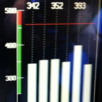 Not-enough-air problems usually manifest as uneven CHTs. The example at right shows cylinder #5 significantly hotter than the rest. Assuming the fuel system is calibrated, and your indicators are functioning correctly, this is a pretty strong hint that cylinder #5 isn't getting enough cooling air. The remainder of this article focuses on modifications to the baffling system. The standard Lancair IV/ IVP cowl and baffle design provides sufficient cooling air to the engine, it just needs a few tweaks to direct the air where it needs to go.
First Things First
Did You Know? Most of the information covered below was originally presented to the Lancair group about ten years ago by George Braly at General Aviation Modifications Inc. (GAMI).
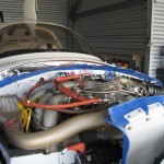
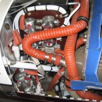
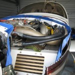
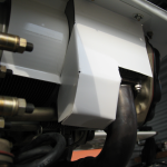
Before proceeding, inspect your baffles. The aluminum and silicone pieces that attach to the engine comprise your baffle system; they form a plenum to capture and direct the air over the cylinder cooling fins and through heat exchangers (intercooler, oil cooler, etc.). If the baffles are in poor shape or were improperly fabricated/installed, then you must begin by repairing them. Lancair offers a baffling kit that may be purchased by itself or as part of a firewall forward kit. The baffling kit is shown in the following pictures.
CLICK TO SEE FULL SIZE
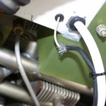
Note how the silicone sections overlap each other and are attached on the sides of the aluminum parts that face toward the engine; the aft silicon sections face forward and the forward sections face aft. These pieces are crucial; they are meant to seal the gaps between the aluminum baffling and the cowl. If mounted improperly they will not form a seal, which is essential in directing the air to the parts that need cooling. The silicone sections should overlap, but should NOT be held together with RTV. A critical part of their functioning is that they expand when “inflated” with air entering the cowl inlets. It is this expansion that allows them to fill the gaps. Bonding them together might interfere with their ability to properly expand and lie flat to make a good air seal against the cowl. Also note that hose penetrations through the aluminum baffle have tight-fitting rubber grommets. The grommets both keep air from leaking through the hole and prevent the hose or line from chaffing.
NOTE: If you are modifying an older baffling set you may find the need to fabricate parts to replace worn pieces. If so, consider using the old parts as patterns for fabricating new ones.
Tweaks
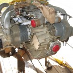
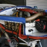
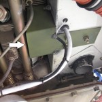
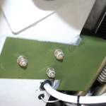
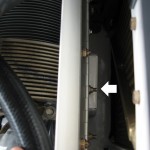
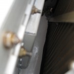
Many builders using Lancair’s baffling kit report problems with cylinders #2 and #5. The picture of the freshly uncrated engine below was taken before the baffling was installed. The arrow below cylinder #5 on the left shows where the cylinder cooling fins will extend below the baffle. Note the depth of the cooling fins above the baffle is extremely shallow. This is also true on the cylinder #2 by the oil cooler. The vertical baffle from Lancair mounts flush against the forward or aft facing portion of the cylinders in these areas, restricting the flow of air through the shallow cooling fins to the portion of the cylinder highlighted by the arrow. This is usually the hottest portion of the cylinder. A small slot cut in the baffle at the location as shown by the arrow in the second photo (shown enlarged in the third photo) reduces cylinder #5 CHT appreciably.
Cylinder #5 & #6 modifications:
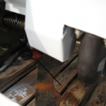
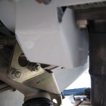
Further modifications are required to keep air in contact with the cooling fins as long as possible. The area marked by the arrow in the photo at right is the aft-bottom side of the aft-most cylinder (cylinder #1). 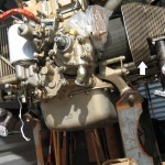 To provide cooling for all parts of cylinder #1, cooling air must enter the cowl intake, flow over the top of the engine, wrap around the cylinder, flow down between the cooling fins on the aft side and then through the cooling fins in the area marked by the arrow. Without modification to the stock baffling the cooling air flows out the bottom without contacting the cooling fins marked by the arrow. Small, U-shaped baffle boxes attached to the bottom of the stock baffles as shown below for cylinders #1, #2, #5 and #6 will enclose the cooling fins on the bottoms of the cylinders, keeping cooling air on them as long as possible.
Cylinder #1 modification:
Cylinder #5 modification:
Cylinder #6 modification:
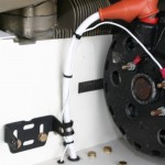
Finally, you must make modifications to the baffling for cylinder #2 and the oil cooler baffling box. The photos below show the oil cooler with the oil cooler baffling box removed for modification. Begin by cutting a hole about 2” x 2” centered on the fin area of cylinder #2 that contacts the oil cooler baffling box. Then fabricate a small hat cover over the hole. Make the hat about 1/4" to 3/8” tall. Like the modifications for cylinders #5 and #6, you also want to add an extension to the oil cooler baffling box to wrap the bottom of the cylinder #2.
NOTE: Unless you are Houdini you must remove the oil cooler baffling box (not the cooler itself but the box enclosing the front of it) to complete this modification . After the cooler is reinstalled you must use RTV to seal the gap between the inboard oil cooler edge and the engine case. This is very important, because without sealing that gap you have a hole big enough to put your five fingers through and cooling air is spilling out. Remember this high pressure air takes the path of least resistance.
Cylinder #2 and oil cooler baffling box modifications:
NOTE: Some have raised the question: Why doesn't Lancair make these modifications to the baffling kits they sell? I always answer the same way: That's a good question!
Contact Jeff at j.edwards [at] lancairowners.com for questions/comments.

